Sunday, March 9, 2008

Texture Splatting With Shaders

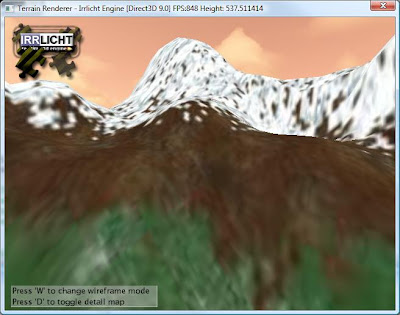
After a few hours of playing around, I finally got a small terrain complete and decided to export a height map with it's corresponding texture map for use in the Irrlicht engine. Irrlicht only allows up to 4 textures for each terrain block so I thought this would be the best way to go. PnP Terrain Creator will bake all the textures, light maps, etc into one texture, which you can stretch over your entire terrain. With my height map and texture map generated, I wrote the code, in Irrlicht, to build the terrain. After building the terrain, I applied the texture map by streching it over the entire block. Here is the result:


Ugh! It looks like crap. Notice how blury the texture looks. This is because there is some disruption in the texture's appearance as it is streched over the terrain. To remedy this situation we can apply a technique called texture splatting. This technique is one that is frequently used in commercial 3D games. Fortunately, PnP Terrain Creator exports the alpha maps required to implement texture splatting.

Texture Splatting
Texture splatting is a technique for texturing a terrain, using high resolution, localized tiling textures which, transition nonlinearly. You can accomplish this by blending an alpha map with each texture in your terrain. This produces unique textures tiled over the landscape, with linear alpha fades between them. This is the effect we need to avoid blurring. This approach will not only prevent bluring but it will also make the transition between textures (ie grass and dirt) look smooth.

One problem I ran into, as previously mentioned, is that Irrlicht only supports 4 textures per terrain block. My terrain has grass, snow, and dirt so I would need 6 textures to implement texture splatting (3 textures for the snow, dirt, and grass, and an alpha map for each texture).

Merging Alpha Maps Using Color Channels

Instead of using one texture for each alpha map, I could use one image and insert each grey scale alpha map into a different RGB channel. This means one texture could store 3 gray scale images. A nice side benefit is that I also save a significant amount of texture memory using this approach.


I can now represent the textures for my terrain using four textures instead of six. I will use three textures for the snow, dirt, and grass and a different RGB channel in one texture for each alpha map. Now that we have the textures set up we need to apply them to the terrain. We could do this in hardware using the fixed function pipeline. However, the fixed function pipeline does not allow for the explicit reading of individual texture color channels in hardware, therefore combined alpha maps would not be possible using the fixed function pipeline and each terrain texture would require it’s own alpha map in texture memory. This means texture splatting must be implemented using a pixel shader.

Texture Splatting With Pixel Shaders
For both HLSL and assembly implementations the general approach is as follows:
  1. Procedurally generate a set of alpha maps for the desired terrain textures (or load pre-generated alpha maps from disk).
  2. Load the set of terrain textures that will be applied into memory.
  3. Initialize the pixel shader.
  4. Set the terrain texture stages for the pixel shader to reference the alpha maps and terrain textures.
  5. Render the geometry using the pixel shader.
High Level Shader Language Implementation
  1. Combined Alpha Map (R= Texture1 Alpha, G=Texture2 Alpha, B=Texture 3 Alpha, A=255)
  2. First layered texture (alpha map stored in the red channel of Texture 1)
  3. Second layered texture (alpha map stored in the green channel of Texture 1)
  4. Third layered texture (alpha map stored in the blue channel of Texture 1)
The textures, once loaded, are associated with the pixel shaders constant table for sampling, and the resulting constant table references are used in the texture stages. Here is the code for the pixel shader I used to implement texture splatting on my terrain in the Irrlicht game engine:

float4x4 matViewProjection : ViewProjection;
float texScale = 10.0;

sampler AlphaMap = sampler_state
{
ADDRESSU = WRAP;
ADDRESSV = WRAP;
ADDRESSW = WRAP;
};

sampler TextureOne = sampler_state
{
MipFilter = LINEAR;
MinFilter = LINEAR;
MagFilter = LINEAR;
ADDRESSU = WRAP;
ADDRESSV = WRAP;
ADDRESSW = WRAP;
};

sampler TextureTwo = sampler_state
{
MipFilter = LINEAR;
MinFilter = LINEAR;
MagFilter = LINEAR;
ADDRESSU = WRAP;
ADDRESSV = WRAP;
ADDRESSW = WRAP;
};

sampler TextureThree = sampler_state
{
MipFilter = LINEAR;
MinFilter = LINEAR;
MagFilter = LINEAR;
ADDRESSU = WRAP;
ADDRESSV = WRAP;
ADDRESSW = WRAP;
};

struct VS_INPUT
{
float4 Position : POSITION0;
float2 alphamap : TEXCOORD0;
float2 tex : TEXCOORD1;
};

struct VS_OUTPUT
{
float4 Position : POSITION0;
float2 alphamap : TEXCOORD0;
float2 tex : TEXCOORD1;
};

struct PS_OUTPUT
{
float4 diffuse : COLOR0;
};

VS_OUTPUT vs_main( VS_INPUT Input )
{
VS_OUTPUT Output;
Output.Position = mul( Input.Position, matViewProjection );
Output.alphamap = Input.alphamap;
Output.tex = Input.tex;

return( Output );
}

PS_OUTPUT ps_main(in VS_OUTPUT input)
{
PS_OUTPUT output = (PS_OUTPUT)0;

vector a = tex2D(AlphaMap, input.alphamap);
vector i = tex2D(TextureOne, mul(input.tex, texScale));
vector j = tex2D(TextureTwo, mul(input.tex, texScale));
vector k = tex2D(TextureThree, mul(input.tex, texScale));

float4 oneminusx = 1.0 - a.x;
float4 oneminusy = 1.0 - a.y;
float4 oneminusz = 1.0 - a.z;

vector l = a.x * i + oneminusx * i;
vector m = a.y * j + oneminusy * l;
vector n = a.z * k + oneminusz * m;

output.diffuse = n;

return output;
}

technique Default_DirectX_Effect
{
pass Pass_0
{
VertexShader = compile vs_2_0 vs_main();
PixelShader = compile ps_2_0 ps_main();
}
}


Texture Splatting - Success!
At this point we have our textures set up and a pixel shader written to implement texture splatting. After writing the code to wire everything up in Irrlicht, I got this result:
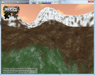


Success! Notice the difference! The textures are no longer blurred and the transition between textures is nice and smooth. Now that I have successfully implemented splatting, I need to figure out a way to seam terrain blocks togeather so that I can build massive terrains. Currently Irrlicht only supports terrain blocks of 128x128. That means you need to break up large terrains into blocks and render them appropriately. This will be my next task.


Sunday, March 2, 2008

Using Vectors to Calculate Orientation

I've got a game character moving around my 3D world but how do I make him face the direction he is moving? This is a common question I see on game development message boards. The answer can be found by using Trigonometry and the arc tangent function or vector mathematics. While both techniques work equally well I am going to demonstrate how to solve this problem using vectors with examples in XNA.


In order to calculate the orientation of an object moving through 3D space, we need to build a matrix for the object's up, right, and forward (also called look vector) vectors. This matrix will be used to calculate the rotation around the Y axis which, is what we need to properly orientate an object in the direction it is moving. The object is already moving in 3D space which, gives us our look vector. In most game engines the Y axis is used for up and down. This means we should be able to use vector 0,1,0 to represent the up vector. Now, that we have our up and forward vectors we should calculate our "right" vector. To find the "right" vector we need to find the cross product of our up and look vectors. The cross product is an operation on two vectors which, results in a new vector that is perpendicular to the two input vectors. This is exactly what we need to find our "right" vector.

Here is some XNA code which, demonstrates what I've discussed so far:

//Look Vector (We know direction of movement)
Vector3 v3L = v3Direction;

v3L.Normalize();

//Up Vector
Vector3 v3U = new Vector3(0.0f, 1.0f, 0.0f);
v3U.Normalize();

//Right Vector
Vector3 v3R = Vector3.Cross(v3U, v3L);
v3R.Normalize();


Notice that we must normalize the vectors after each calculation. Since these vectors represent orientation we need to factor out the magnitude component. The Normalize method of the vector class (in XNA) helps us do just that. To make this more clear, the vector 0,3,0 gives us an orientation pointing up the Y axis with a magnitude of 3. For this example, all we care about is orientation so there is no difference between 0,3,0 and 0,1,0. However, 0,1,0 makes mathematical operations on orientation vectors easier. By normalizing the vector we factor out the magnitude component so we can focus on orientation.

The next step is to plug these vectors into a Matrix so that we can use this matrix in calculating the object's final world position. Here is the XNA code to accomplish this:

Matrix YRot = new Matrix();
YRot.M11 = vR.X; YRot.M12 = vR.Y; YRot.M13 = vR.Z; YRot.M14 = 0.0f; //Right
YRot.M21 = vU.X; YRot.M22 = vU.Y; YRot.M23 = vU.Z; YRot.M24 = 0.0f; //UpYRot.M31 = vL.X; YRot.M32 = vL.Y; YRot.M33 = vL.Z; YRot.M34 = 0.0f; //LookYRot.M41 = 0.0f; YRot.M42 = 0.0f; YRot.M43 = 0.0f; YRot.M44 = 1.0f;


We now have a matrix which, represents our objects orientation in 3D space. This orientation matrix should match the direction of movement. The next step is to include this matrix in the object's world position calculation. The code example below assumes that the objectPosition variable is being constantly updated in the game loop. Our goal now is to calculate the object's final world position, scale, and orientation.

Matrix matTranslation = Matrix.CreateTranslation(objectPosition);
Matrix matYRotation = YRot

Matrix worldMatrix = matYRotation * matTranslation;

The order of operations is important when concatenating matrices. The correct order should be rotation, scale, and translation. This is because all operations take place at the world's origin. If the object is translated before it is rotated you will get an orbit effect around the world's origin rather than the rotation we are trying to achieve.

We have almost achieved our goal. The worldMatrix should now hold the rotation, scale, and position of our object in world space. Additionally, the orientation of our object should match the direction the object is moving. All we have to do now is project our object to the computer screen. The first step in this process is to translate the object from world space to view space. Remember that we have a camera in our scene and objects need to be translated in reference to the camera's position. This is called translating the object from the world coordinate system to the view coordinate system. Once this is complete, we need a way to project our 3D scene to a 2D screen. To do this, we should translate objects from the view coordinate system to the screen coordinate system.

Vector3 cameraPosition = new Vector3(0.0f, 0.0f, 10.0f);
Vector3 cameraLookAt = new Vector3(0.0f, 0.0f, 0.0f);


Matrix viewMatrix = Matrix.CreateLookAt(cameraPosition, cameraLookAt, Vector3.Up);

Matrix projectionMatrix = Matrix.CreatePerspectiveFieldOfView(MathHelper.ToRadians(45.0f), (float)GraphicsDevice.Viewport.Width / (float)GraphicsDevice.Viewport.Height, 0.0005f, 10000.0f);

At this point we have the worldMatrix variable which holds the rotation, scale, and position of our object in world coordinate space. We also have the viewMatrix variable which represents view coordinate space and the projectionMatrix variable which, holds the information required to project our 3D scene to a 2D screen. All we have to do, at this point, is concatenate our matrices together to project our object to the screen.

Matrix worldViewProjection = worldMatrix * viewMatrix * projectionMatrix

The worldViewProjection matrix now holds all the information required to get your object from 3D world space to your computer screen. What you do next depends on the game engine you're using. In XNA you would pass the worldViewProjection matrix into a pixel/vertex shader for rendering.